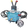
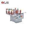
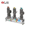
Installing and maintaining ceramic high voltage disconnectors, such as the GW4-40.5 Ceramic High Voltage Disconnector, requires careful adherence to best practices and technical guidelines to ensure safety, reliability, and optimal performance in electrical systems.
Installation Steps for GW4-40.5 Ceramic High Voltage Disconnector
Installing a ceramic high voltage disconnector like the GW4-40.5 Ceramic High Voltage Disconnector involves several critical steps to ensure proper functionality and safety. According to installation guides from industry leaders like ABB, the first step is to conduct a thorough inspection of the disconnector and its components to verify their integrity and condition. This includes checking for any signs of damage during transportation or storage.
Next, positioning the GW4-40.5 Ceramic High Voltage Disconnector disconnector correctly within the electrical system is crucial. Siemens recommends placing the disconnector in a location that allows easy access for maintenance and operation while ensuring compliance with clearance and safety distances specified in regulatory standards. Proper alignment and secure mounting of the disconnector prevent mechanical stress and ensure stable operation during switching operations.
After positioning, connecting the electrical cables to the GW4-40.5 Ceramic High Voltage Disconnector disconnector terminals follows manufacturer-specific instructions and using appropriate tools to avoid damaging the ceramic components. Schneider Electric emphasizes the importance of verifying electrical connections for tightness and conducting insulation resistance tests to confirm the integrity of the installation. These steps help mitigate the risk of electrical faults and ensure the disconnector operates efficiently within the electrical system.
Step 1: Planning
Prior to starting the establishment interaction, it's pivotal to assemble every essential device, gear, and documentation. Make sure that the installation area is clear and easy to find, and that there is enough room for moving the disconnector around and mounting it.
Devices and Hardware: Assemble devices, for example, torques, screwdrivers, protecting gloves, wellbeing goggles, and a force wrench aligned for high voltage applications.
Documentation: Examine the installation manual, safety instructions, and technical specifications of the disconnector.
Security Measures: Protect yourself from electrical dangers by donning appropriate personal protective equipment (PPE), such as safety goggles and insulating gloves.
Step 2: Mounting the Disconnector
Situating: Determine precisely where GW4-40.5 Ceramic High Voltage Disconnector should be mounted. During operation, make sure it is mounted on a level, stable surface that can support its weight and mechanical stress.
Alignment: Adjust the disconnector in accordance with the manufacturer's instructions, making sure that all of the mounting holes are positioned in line with the surface of the installation.
Securing: Utilize proper clasp (normally fasteners or screws) to safely affix the disconnector to the mounting surface. Fix the latches equitably to guarantee uniform tension across the mounting focuses.
Insulation: In order to comply with safety regulations and prevent accidental contact with live parts, ensure that there is sufficient clearance and insulation around the disconnector.
Step 3: Points of Connection for Electrical Wiring
Distinguish the approaching and active terminals of the disconnector in light of the framework's wiring chart and the maker's directions.
Preparation of Cables: Set up the links by stripping protection according to the predetermined length and pleating hauls or connectors safely onto the link closes.
Connection to a Terminal: Connect the prepared cables to the disconnector's appropriate terminals. Utilizing the recommended torque values, ensure that connections are secure and tight to avoid mechanical failure and overheating.
Grounding: Check legitimate establishing as indicated by electrical codes and principles. Check to see that the grounding terminal of the disconnector is securely connected to the installation's grounding system.
Step 4: Visual Inspection During Testing and Installation
Direct a visual examination of the whole establishment to guarantee that all associations are secure, there are no apparent indications of harm, and all parts are appropriately adjusted.
Utilitarian Testing: Activate the disconnector in accordance with the instructions and operating procedures provided by the manufacturer. Work the disconnector through its full scope of movements (opening and shutting) to confirm smooth activity.
Testing of Electricity: Under normal operating conditions, conduct electrical tests to ensure proper continuity, insulation resistance, and the absence of leakage current.
Security Checks: Verify that all of the safety features, like position indicators and interlocks, work as intended. Check that warning labels and signs are in place in accordance with regulations.
Step 5: Handover documentation and documentation:
Completely document the disconnector's installation and operational parameters with as-built drawings, test reports, and installation records.
Training: Give preparing to support work force on the activity, upkeep, and crisis methods connected with the disconnector.
Handover: Complete the establishment handover process by acquiring close down from approved work force affirming the effective establishment and charging of the GW4-40.5 disconnector.
Maintenance Practices for GW4-40.5 Ceramic High Voltage Disconnector
Maintaining the ceramic GW4-40.5 Ceramic High Voltage Disconnector is essential for prolonging its lifespan and ensuring reliable performance over time. Regular inspection, as recommended by GE Power, involves checking for signs of wear, corrosion, or contamination on ceramic surfaces and electrical contacts. Cleaning these components using approved methods and materials prevents degradation and ensures optimal electrical conductivity.
Furthermore, lubricating mechanical parts and inspecting operating mechanisms for smooth operation are integral maintenance tasks. According to technical specifications from ABB, applying manufacturer-recommended lubricants to moving parts of the GW4-40.5 Ceramic High Voltage Disconnector disconnector reduces friction and wear, enhancing its operational reliability and extending maintenance intervals.
Lastly, conducting periodic testing and diagnostics, such as insulation resistance tests and mechanical operation tests, is critical. These tests, as outlined in guidelines from Siemens, validate the disconnector's functionality and identify potential issues before they escalate. Documenting maintenance activities and test results ensures compliance with regulatory requirements and facilitates proactive maintenance planning to minimize downtime and optimize system performance.
Conclusion
In conclusion, proper installation and maintenance of ceramic high voltage disconnectors like the GW4-40.5 Ceramic High Voltage Disconnector are essential for ensuring operational safety, reliability, and longevity in electrical systems. By following established installation procedures, conducting regular maintenance checks, and adhering to manufacturer guidelines, electrical professionals can maximize the performance of disconnectors and mitigate risks associated with high voltage operations. For more information on installing or maintaining ceramic high voltage disconnectors, please contact us at austinyang@hdswitchgear.com.
References
1. ABB. (Year). Installation guide for ceramic high voltage disconnectors.
2. Siemens. (Year). Maintenance practices for high voltage disconnectors.
3. Schneider Electric. (Year). Electrical connection and insulation testing for disconnectors.
4. GE Power. (Year). Maintenance strategies for high voltage equipment.