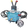
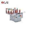
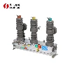
The load switch-fuse combination switchgear is a high-voltage switchgear widely used in the protection of distribution transformers. It combines a load switch and a fuse, with the load switch interrupting normal load current and the fuse interrupting short-circuit fault current, achieving a balance between functionality and cost.

Core Working Principle
The high efficiency of combined electrical appliances lies in the seamless coordination between the load switch and the fuse. This coordination is achieved primarily through two methods, revolving around a key technical indicator.
There are two coordination methods:
Striker Operation:The fuse contains a "striker." When the fault current is large and the fuse blows, the built-in striker immediately pops out, forcibly pushing the load switch to trip via a mechanical linkage, preventing the equipment from operating with a single phase. This is the most basic and reliable coordination method.
Trip Unit Operation:The load switch itself is equipped with a "shunt trip unit." When the overload current is small, a relay or other protective device sends a command to activate the shunt trip unit, causing the load switch to trip and preventing damage to the expensive fuse due to a minor fault. This method offers a higher level of intelligence.
Key Technical Indicator: Transfer Current
This is a crucial parameter for evaluating the performance of a combined electrical appliance, determining which component, the load switch or the fuse, will handle the fault.
You can think of the transfer current as a "task handover point":
Current < Transfer Current: The fuse is responsible for interrupting the first phase fault; the remaining two phase currents are handled by the load switch.
Current > Transfer Current: All three-phase fault currents are quickly interrupted by the fuse; the load switch only performs a post-fault trip.
The division of responsibilities among the combined electrical appliances when switching on and off different currents is as follows:
| Fault current range | Who is responsible for interrupting the fault? | Brief description of the working process |
|---|---|---|
|
Normal load current |
Load switch |
The circuit breaker is responsible for the daily switching on and off; the fuse does not participate in this process. |
|
Small overload current |
Load switch |
The fuse is not damaged by tripping via the shunt trip unit or manual operation. |
|
Transfer current region |
Load switch + fuse |
The fuse breaks the first open phase and triggers the striker, while the load switch breaks the remaining two phases. |
| Large short-circuit current | Fuse | The three-phase fuses melt rapidly and simultaneously within half a circuit cycle, limiting the hazards of short-circuit current. |
How to Correctly Select Combined Electrical Equipment
Correct selection is key to ensuring the long-term safe and reliable operation of equipment. You can refer to the following three steps:
Estimate the transfer current based on the transformer capacity
This is the first step in selection. For example, the estimated transfer current of a 10kV, 800kVA transformer is approximately 685A. You need to ensure that the rated transfer current of the selected combined electrical equipment is greater than this estimated value.
Select the appropriate load switch type
General type (gas-generating, compressed air-based): Simple structure, low cost, transfer current capacity is usually around 800-1000A, suitable for transformers of 800kVA and below.
Frequency type (vacuum, SF6): Strong arc-extinguishing capability, long electrical life, transfer current capacity can reach 1500-3150A, suitable for 1250kVA and below, and frequent operation applications. For transformers with a capacity exceeding 1250kVA, it is generally recommended to use circuit breaker protection.
Match the rated current of the fuse
A larger fuse is not necessarily better; it must be matched with the transformer capacity. For example, a 500kVA transformer is typically equipped with a 50A fuse, an 800kVA transformer with an 80A fuse, and a 1250kVA transformer with a 100A fuse. The rated current of the fuse must be less than the rated current of the load switch.
Summary
The core of a load switch-fuse combination appliance lies in the word "coordination." It utilizes the load switch to handle daily on/off switching and the fuse to quickly cut off serious faults, achieving high cost-effectiveness and high reliability. In practical applications, as long as the key element of "current transfer" is grasped, and the load switch and fuse are correctly matched according to the transformer capacity and operating requirements, the long-term safe and reliable operation of the equipment can be ensured.
Contact Us
Shaanxi Huadian Electric Co., Ltd.'s FZRN25A-12D/T200-31.5 indoor high-voltage vacuum load switch-fuse combination appliance, through innovative technological integration, achieves perfect coordination between the load switch and the fuse, providing a protection solution for 12kV distribution networks comparable to circuit breakers, while maintaining superior economic efficiency. We have been deeply involved in the high-voltage electrical appliance field for many years, providing not only products but also full life-cycle technical support. From precise matching during the selection phase (calculating transfer current based on your transformer capacity) to installation and commissioning, and after-sales maintenance, the Huadian professional team is always with you. Please contact us:pannie@hdswitchgear.com.